Rotar47
Contents
Antenna rotator 4.7
Obsoleted by Rotar 5.
Rotar is digitally controlled antenna rotator. It can drive DC commutator motors, AC 2-phase motors or linear motor (superjack) for elevation. It has two independent channels so it can drive two azimutal motors or one azimutal and one elevation motor. Sensors are magnetical contact providing pulses. Each channel has two contacts - one for pulses and second for synchronization. Human control is done by matrix keyboard 4x4 and HD44780 compatible display. It can communicate with PC via TTL-level serial port. Available accessories is USB converter for control using Tucnak.

Gallery
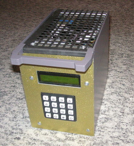
Control box made by OK1USW
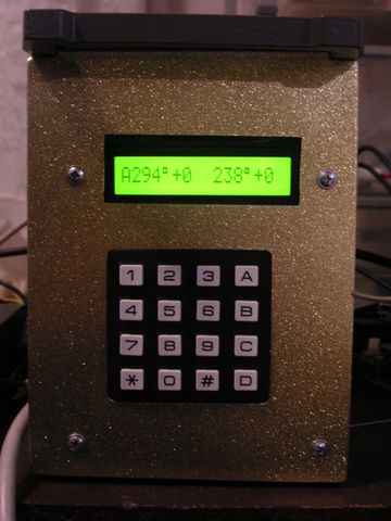
Front view display and keyboard
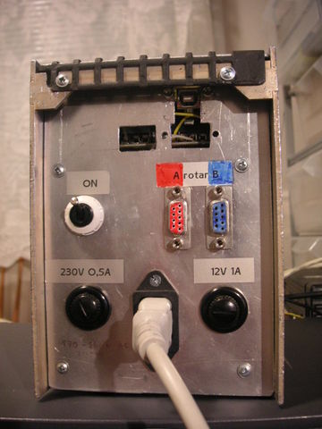
Back panel with connectors
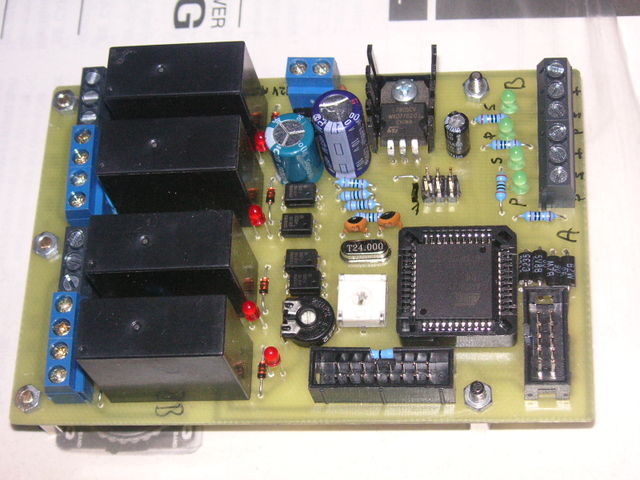
Finished board


Circuit diagram

PCB
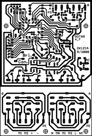
PCB top side (600 DPI)
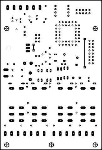
PCB bottom side (600 DPI)
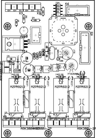
Components placement top
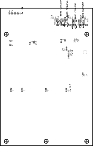
Components placement bottom


Note: 600 DPI have images in Full resolution, MediaWiki uses thumbnails.
Sensors
Typical sensor consists of two contacts. They switching "live" wire to ground.
Pulses contact
It generates pulses depended of antenna rotation. Pulses does not depend on rotation direction. Direction is taken from polarity of motor drive.
We use various resolution from 480 to 1060 pulses per 360 degrees. Length of ON and OFF time must be longer than about 2 ms (state is sampled by timer with period 480 Hz). So good idea is to have pulse ratio 1:1.
Typically we use magnet glued on applicable whell in gear. In gears with no space and/or magnetic wheel we used optical sensor. But be aware of RFI if electronics circuit of sensor is near to antenna.
Synchronization contact
Pulses can be lost. So there is synchronization contact at known angle. When this contact is switched on, the rotator is synchronized to the known angle. Switch-on angles are two. First from positive, second for negative direction. Good ide is to have known synchronization angle in direction where operator beams antenna often.
We use magnet on the mast or lobe with switch.
Synchronization contact for elevation must turn on and off between lower and upper stops for both directions.
Pinout for old sensor
Old sensors used with rotators "Sever" uses 9-pin Cannon (D-SUB9) and has following pinout:
- Pulses A
- Sync A
- Pulses B
- Sync B
- +12V
- GND
- GND
- GND
- GND
User control
Display

- A means the channel A is active.
- When rotation is in progress, the direction arrows are showed. Diamond sign means you're reach the stop.
- 294° is current angle
- +0 is current turn count. You can see distance from stops (if you know them :-).
Right half has same sense for second channel.
Keyboard
Operator can control rotator using matrix keyboard 4x4:
- * - While pressed, antenna is moving in negative direction.
- # - While pressed, antenna is moving in positive direction.
- A - Switch rotator A active. In elevation mode raise elevation.
- B - Switch rotator B active. In elevation mode lover elevation.
- C - Stop rotating, deletes number as Backspace, escapes from menu
- D - Used as Enter for angle confirm or in menu.
- 4 - Turn antenna by 10 degrees in negative direction
- 6 - Turn antenna by 10 degrees in positive direction
- 7 - Turn antenna by 20 degrees in negative direction
- 9 - Turn antenna by 20 degrees in positive direction
- three digits number - Turns antenna to entered angle.
- 399 - Enter menu
Motor types
DC commutator

AC 2-phases

Menu
Menu is run by entering angle 399. You can move between menu items pressing A and B, alternativelly by 2 and 8. Next level is entered by D, escape is C.
When configuring, some tasks are not independent. I you are not familiar with implemenation details, please use configuration items in numbered order.
- Reset 2xAzim. - Initialize rotator to control two independent azimuthal motors.
- Reset Azim+Ele - Initialize rotator to control one azimuthal and one elevation motors.
- Autoconfig - Performs automatic intelligent Auto configuration.
- Clear stops - Clear all stops (ends of rotation). See later.
- Turn left (-1) - Decrement angle by 360 degrees. It's not important, is good to have turn count near to zero.
- Turn right (+1) - Indrement angle by 360 degrees. Same sa above.
- Fix angle - Use after installation. Turn antenna to the known direction (using compass or beacon) and enter this angle here. Warning: In new installation first turn the antenna over synchronization contact.
- Left stop - Turn antenna left (negative) for 1-2 turns respeting antenna cable damage and enter this item. Rotator will remember angle and prevent to turn behind it.
- Right stop - As above.
- Comm address - Communication address for PC connection. Normally use 240. Decrement and increment address by 4 and 6.
- Debug - Dump internal variables. Use A and B to switch channels. Use 2 and 8 for item switching.
- dbgp - pressing 4 and 6 you can interconnect input pulse pins with speaker connected to CPU pin P1.5. Usable to debug sensor problems by ears. Speaker is not designed on PCB.
Auto configuration
Azimuth
All configuration is done automatically. Motor will make about -1 to +2 turns so keep it in the mind. If motor makes more turns, you have probably broken synchronization sensor. Press C to abort operation.
Elevation
Note this description is made some years after coding. Maybe it can be inaccurrate. Function itself was not very tested, we use it only once for 3cm RS.
- Use A and B to move to the upper stop. Press D to confirm.
- Move motor to lower stop.
- Rotator will go up and down to sniff synchronization. Stops at lower stop.
- Last step is to teach rotator about real angle. You must enter 20 points for linear approximation.
- Press A and B to set elevation.
- Get real elevation angle (using water level, angle gauge or something) and set it by 2 and 8.
- Confirm angle by D