Davac4: Difference between revisions
Jump to navigation
Jump to search
No edit summary |
|||
| Line 26: | Line 26: | ||
All data: [[File:Davac4-ok2jtb.zip]] | All data: [[File:Davac4-ok2jtb.zip]] | ||
=Made by OK1UDC & OK1UGE= | =Made by OK1UDC(SK) & OK1UGE= | ||
<gallery mode="packed" heights="320px"> | <gallery mode="packed" heights="320px"> | ||
Image:Davac4_UDC_UGE_1.JPG|Front panel | Image:Davac4_UDC_UGE_1.JPG|Front panel | ||
| Line 34: | Line 34: | ||
''Note OK1ZIA: better use USB-B type connector'' | ''Note OK1ZIA: better use USB-B type connector'' | ||
=Combined Davac4 and contest machine RPi= | |||
Guys from OK1RPL made this compact contest solution. | |||
<gallery mode="packed" heights="320px"> | |||
Image:IMG_20190122_144139027.jpg | |||
Image:IMG_20190123_185415964.jpg | |||
Image:IMG_20190123_185427268.jpg | |||
Image:IMG_20190123_191712849.jpg | |||
Image:IMG_20190131_112445866.jpg | |||
Image:IMG_20190131_112456794.jpg | |||
</gallery> | |||
Revision as of 10:51, 31 January 2019
Davac 4.0
Davac 4 was succesfully built by OK1USW, OK1UGE and OK2JTB.
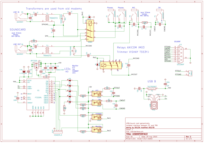
Circuit diagram
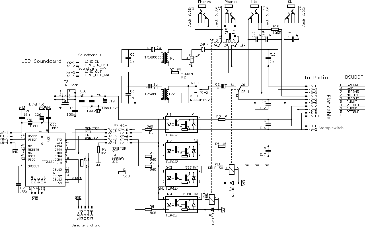
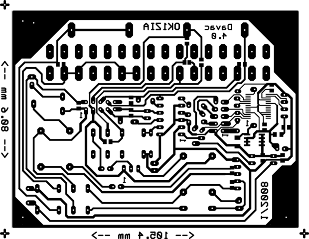
PCB
-
PCB bottom side (600 DPI)
-
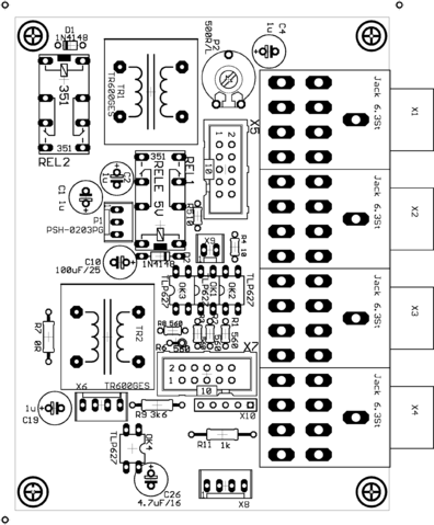
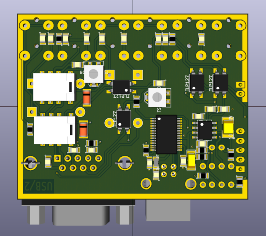
Components placement top
-
Components placement bottom
Note: 600 DPI have images in Full resolution, MediaWiki uses thumbnails.
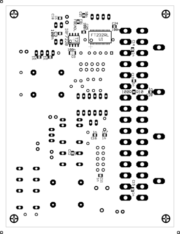
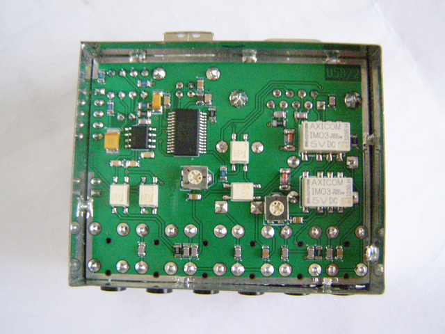
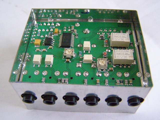
SMT variant by OK2JTB
-
Top side
-
Bottom side
-
Photo 1
-
Photo 2
-
Photo 3
-
Schematics
All data: File:Davac4-ok2jtb.zip
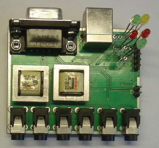
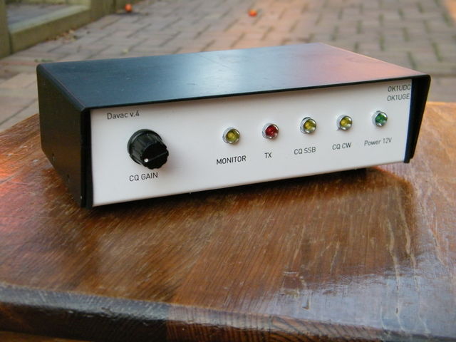
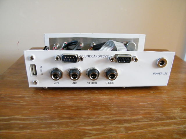
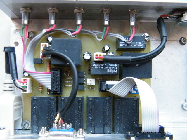
Made by OK1UDC(SK) & OK1UGE
-
Front panel
-
Back panel
-
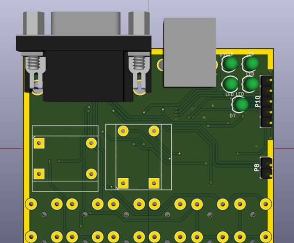
Components side
Note OK1ZIA: better use USB-B type connector
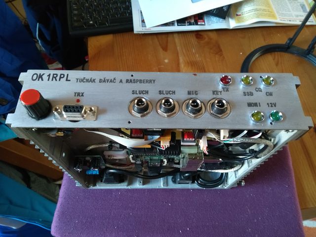
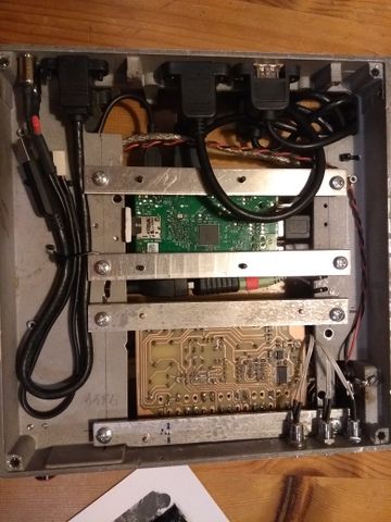
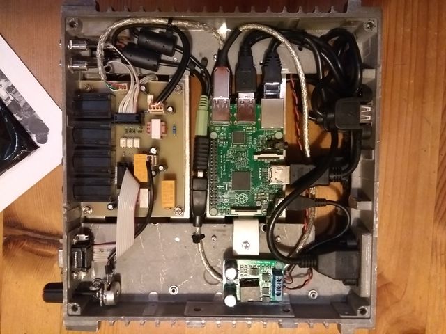
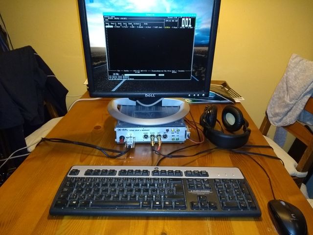
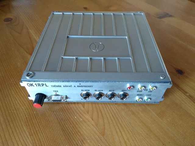
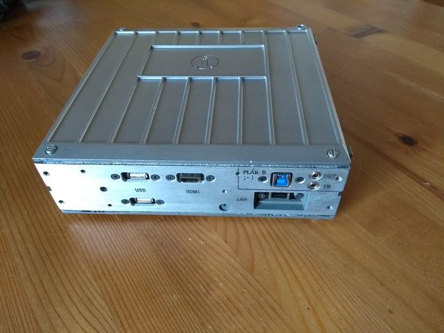
Combined Davac4 and contest machine RPi
Guys from OK1RPL made this compact contest solution.
