Rotar47: Difference between revisions
Jump to navigation
Jump to search
No edit summary |
No edit summary |
||
| Line 5: | Line 5: | ||
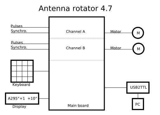
[[Image:Rotar47.png|none|frame|Principe of rotator 4.7]] | [[Image:Rotar47.png|none|frame|Principe of rotator 4.7]] | ||
=Gallery= | |||
<gallery> | <gallery> | ||
Image:Rotar47usw_1.jpg|Rotator made by OK1USW | Image:Rotar47usw_1.jpg|Rotator made by OK1USW | ||
| Line 10: | Line 11: | ||
Image:Rotar47usw_back.jpg|Back panel with connectors | Image:Rotar47usw_back.jpg|Back panel with connectors | ||
</gallery> | </gallery> | ||
=Circuit diagram= | |||
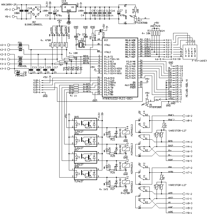
[[Image:Rproc47s120.png|none|frame|Circuit diagram of rotator 4.7]] | |||
Revision as of 19:03, 21 March 2009
Antenna rotator 4.7
Rotar is digitally controlled antenna rotator. It can drive DC commutator motors, AC 2-phase motors or linear motor (superjack) for elevation. It has tow channels so it can drive two azimutal motors or one azimutal and one elevation motor. Sensors are magnetical contact providing pulses. Each channell has two contacts - one for pulses and second for synchronization. Human control is done by matrix keyboard 4x4 and HD44780 compatible display. It can communicate with PC via TTL-level serial port. Available accessories is USB converter for control using Tucnak.

Gallery
-
Rotator made by OK1USW
-
Front view display and keyboard
-
Back panel with connectors
Circuit diagram


