CI-V interface: Difference between revisions
No edit summary |
|||
| Line 9: | Line 9: | ||
Solder only one of connectors X1, X2. X1 is standard USB-B female, X2 can be used if you want to use other cable than A-B. | Solder only one of connectors X1, X2. X1 is standard USB-B female, X2 can be used if you want to use other cable than A-B. | ||
=Note= | |||
If communication errors occur during tune, you have to disable CI-V transceive mode. For IC706: | |||
* Turn the radio off | |||
* Press LOCK | |||
* Turn the radio on | |||
* Rotate M-CH knob to menu item '''36 CI-V TRN''' | |||
* Rotate main tunning knob counterclockwise to set '''oFF''' | |||
* Turn radio off and on | |||
=PCB= | =PCB= | ||
Revision as of 08:29, 5 October 2014
Tested with: IC-706MKIIG, IC-7400
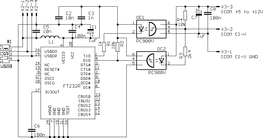
Schematics

I've used my favourite USB to serial converter FT232RL in recommended wiring. After many experiments I've found it is not possible to make interface without supply from radio. Radio provides voltage through high impedance. It can work statically but reaching real communication speeds is impossible, rise edges are too slow. Supply can be about +5 to +12V . For my purpose best fits +8V from microphone connector (pin 1) next to the CI-V jack (on IC706 family).
Solder only one of connectors X1, X2. X1 is standard USB-B female, X2 can be used if you want to use other cable than A-B.
Note
If communication errors occur during tune, you have to disable CI-V transceive mode. For IC706:
- Turn the radio off
- Press LOCK
- Turn the radio on
- Rotate M-CH knob to menu item 36 CI-V TRN
- Rotate main tunning knob counterclockwise to set oFF
- Turn radio off and on
PCB
-
PCB of USB2CIV
-
Parts side A
-
Parts side B
Photos
On the pictures is version for IC-706MKIIG - supply is connected to microphone RJ-45, pin 1.
Used box can be obtained here: http://krabicky.cz/viewproduct.php?=SID&productid=200


